
In the last post I explained how I made the LED timing device for measuring the shutter lag on my DSLR.
The first way I wanted to test triggering the camera was by using the IR remote control. If I could get good results with that, then I wouldn’t even have needed to bother making a cable. Sadly it soon became pretty apparent that IR wasn’t going to cut it.
The second part of the testing was hardwired. I examined controlling the DSLR using:
- a direct connection — Quick and dirty, but possibly has issues with voltage levels and noise.
- using a 5V mechanical relay — Much cleaner, but might introduce timing jitter due to ‘switch bounce‘.
- and an opto isolator — This is the ‘proper’ way to do it, and I left this till last, since it’ll stay on the rig when I’m finished.
I then spent quite a bit of time with a pen and paper while the DSLR and shutter rig did their thing.
There’s also a few other things we need to know about the camera which will end up influencing the timing.
- ‘Mirror lock up’ — A DSLR has a moving mirror that drops down in front of the sensor, which directs the light to the viewfinder. When the shutter button gets pressed, the mirror quickly flips up and the shot it taken. ‘Locking up’ the mirror should in theory make it faster, since it removes a step in the process.
- ‘Live View’ — when the mirror is flipped up and the sensor is fed to the camera’s screen live.
- Auto focus/Manual focus — In auto focus mode the camera moves the focus motor forwards and backwards until it detects the greatest detail. This all takes time, and adds to the variability in the delay. Manual focus should be the most repeatable option.
The results:
And here’s what the results look like for my Canon 550D camera (click for large version):
 This was quite surprising to see. Here’s a few lessons:
- No matter what I do, it sucks. Even in the best case, with everything in manual and a wired remote there’s still 100ms variation in the output.
- IR seems to introduce a lot of uncertainty in the output. This was surprising, since I coded the arduino to only output the IR code a single time (as any looping might introduce abiguity over timing)
- Live view & lockup didn’t help at all, in fact they seemed to make it worse, which suprised me.
I was a bit confused here. Was this just my camera, or does every DSLR behave this way? I set out to borrow as many as I could could get in a couple of days. Here’s the results:
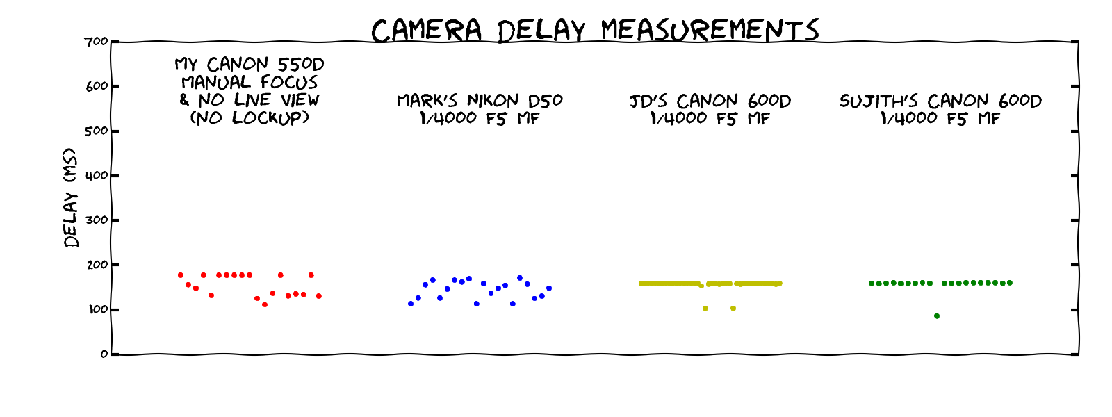
The Nikon D50 was released way back in 2005, so this is a bit of an unfair comparison to Nikon. The two 600D units I played with behaved a heck of a lot better, which is surprising, since the model is only a year later than my camera, which came out in 2010.
Ah well, at least I have my answer. The water drop photography was misbehaving because my camera is at fault. Now I know how the camera acts, I can work around it by keeping the shutter open longer, and rely on lighting everything with a flash instead. The only downside is I have to make a bit of a ‘tent’ around the rig to eliminate the stray light. The other camera we were using could work without the tent setup.
I’ll post some photos of the succesful drop photography shortly.
And here’s the python code and raw data used to generate the graphs:

Love the analysis, and especially love the xkcd style graphs
LikeLike
Cheers, Kean 🙂
LikeLike
Pingback: Water drop photography | Tinkerings
Hi, did you find the lag was consistent on any one camera? Could it be calibrated out by measuring each cameras lag and delaying the triggering of the faster ones?
LikeLike