
I’ve been playing around with tangible versions of the Bloch/Poincare sphere previously, and I think breaking polarization down into 3 orthogonal dimensions (Stokes vectors) yields such a useful mental model of what’s happening with various complex systems.
In the same vein, I’ve been meaning to come up with a tangible model of what waveplates do to polarization of light. Waveplates are a crucial building block of so much in physics, from microscopes to cameras to quantum computers.
While the Poincare models I made before were handy as a reference, to model a system with multiple filters you have to pick up and rotate the sphere several times, simulating axes at various points. I specifically wanted to find something more direct, and that could be continuously played with to ‘steer’ to a given result. Something you could put in front of a student and say “OK, given horizontal polarization as an input, exactly how would you set up the equipment to convert that to 45 degrees?”
Here’s what I’ve got for the Half-Wave Plate. The two gears rotate around each other, and the coordinate labels on the outer gear swivel as it does so. The input coordinate system is on the base, and the outer gear shows the output frame.
By playing with it for a second, you can see how it shows how Right and Left circular polarizations are always swapped, but by rotating the “fast axis” of the waveplate, you can choose how the linear polarizations are converted.
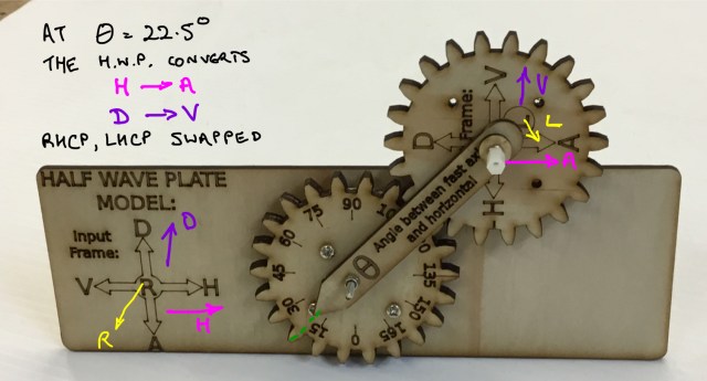
Half-wave plate model with gears
Along the same lines, here’s what I came up with for the Quarter-Wave Plate:
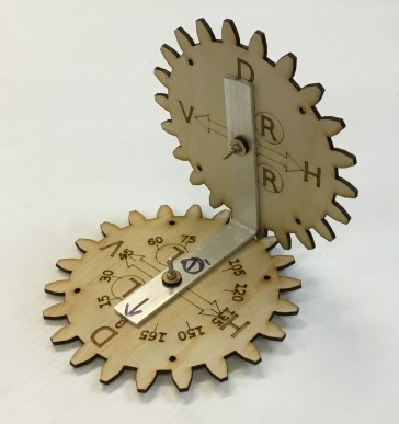
Quarter-wave plate model with gears
Here’s a quick application of quarter-wave plates, using three of them as a polarization controller that can put any polarization state into any other polarization state. (Side note: polarization controllers are more commonly made using a quarter-half-quarter arrangement of plates, not a quarter-quarter-quarter as shown here, but this has sufficient degrees of freedom to do this job)

Polarization controller, in this case consisting of three linked quarter-wave plates. By adjusting the three angles, any polarization can be converted to any other polarization
Before we test the bold claim about three QWPs doing everything, let’s do a sanity check on the behaviour of the lasercut device. A waveplate shouldn’t affect polarization of light which perfectly matches either the fast or slow axis, so let’s set up the plate with theta=0, and see what happens:
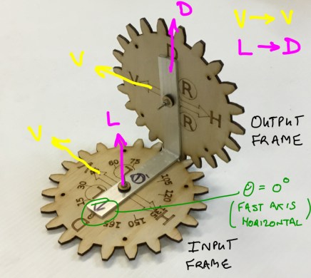
Quarter wave plate test
As you can see vertical (V) light is unaffected, and left circular (L) light is converted to +45deg diagonal (D) light, as expected.
What is we combine two waveplates, and see if we can convert Left-Circular (L) light to Right-Circular (R) light? After playing around with the gears for a few seconds, this configuration seems to work nicely:

Two Quarter-Wave Plates acting as a Half-Wave Plate, only because their angles match
The nifty thing to note here is that the angle of the first waveplate (120*) matches the second (120*), indeed that’s the only way to make the gears flat. This makes sense, as having them at the same angle is how to turn two QWPs into a HWP.
Alternately if we put the two plates at 90* to each other, then the second plate would ‘undo’ all the rotations of the first plate, and the polarization would be back where it started.
OK, now for a challenge. Here’s a task I picked at random, including at least one ‘weird’ direction to make it harder. Can three QWPs do this? Let’s define our task:
- Flip left and right circular polarizations. (LHCP <–> RHCP )
- Convert 67.5 degree light (halfway between Diagonal and Vertical) into Horizontal
First, I bolted three QWP models together: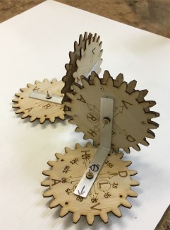
and then spent a while fiddling until I got it lined up with the goal:
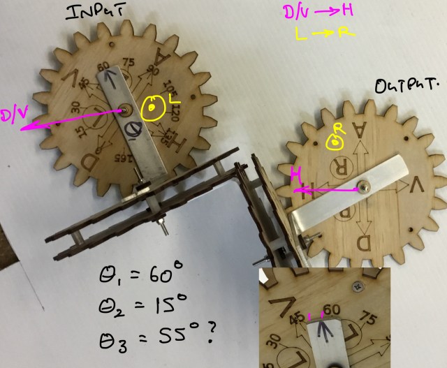
Calculating the correct waveplate settings to do an arbitrary rotation of the polarization.
I’m eyeballing it, but I’m going to call the three angles 60 degrees, 15 degrees and 55 degrees respectively. (The camera parallax is a bit misleading too, they look more parallel in real life. )
So that would mean we set up the parts on the optical table like so:
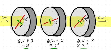
How to double check our answer? It kinda looks right sitting on the table, but would it work if you tried it in the lab with real optics? Let’s do Mueller calculus with those numbers and predict what would happen if we shine LHCP and D/V light in there.
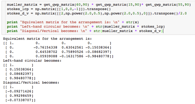
Predicting the result with QWPs oriented at 60, 15 and 55 degrees
The expected number for right-hand circular is [1,0,0,1], which is pretty close to what we got, with just a smidge too much linear polarization. And the expected number for horizontal is [1,0,1,0], which is extremely close.
For lasercut plywood and hastily bent pieces of aluminium, I’m pretty happy with that.
Files are here for the Half Waveplate: https://www.thingiverse.com/thing:3076339
and the Polarization Controller: https://www.thingiverse.com/thing:3076410

Pingback: I’m on EEVBlog | Tinkerings