Organising box for watercolour inks

Here’s a quick lasercut project. Paul from RnD updated the inkscape box generator to include inside tabs, and I took the opportunity to tidy up my collection of old watercolour inks.

Here’s the pieces cut out:  Pieces ready for assembly

And glued together. I put a few drops of each on the side and wiped it to show each phial’s colour:

Finished watercolour ink holder

The code is up here:

https://github.com/paulh-rnd/TabbedBoxMaker

Posted in Uncategorized | Leave a comment

Quick and dirty vacuum gauge

I’ve been playing around with vacuum the last couple of weeks. While I was waiting for more parts and a proper vacuum gauge arrive from eBay, I was impatient to get at least some measurements of how good the vacuum was in the system.

I started thinking of ways to improvise a pressure sensor.

marshmallow gauge

Marshmallows provided a great visual indication that, yes, there was vacuum aplenty. But it was a bit less quantitive than I hoped.

I played around a bit with Pirani gauges, which are a way to use resistors as pressure sensors. That wasn’t too bad, and I’ll detail those in a later post when I write up the chamber itself. But it seemed to me that there should be some easier way of getting an indicator.

I could always see how high water could be drawn up into a tube. Although for a decent vacuum, that would mean about 10m high of water, which was taller than any building I had access to. You can make the necessary height shorter by using different fluids (mercury would require less than a meter tall gauge), but I couldn’t work out any combinations that would be both safe and practical.

I eventually came up with the idea of a Bourdon tube using plastic I had laying around. This seemed to worked pretty nicely:

bourdon gauge

Without another gauge to calibrate it against, I could only test it by bleeding air into and out of the system slowly using the valves. It seems surprisingly linear, though.

You can even make a direct digital readout by driving the tube onto an electric scale!

pressure gauge from bourdon tube and digital scale

Posted in Uncategorized | Leave a comment

Bell jar travel case

I recently have been playing around a bit with vacuum systems.

I got a lovely bell jar on eBay, but I was worried it’d get damaged every time I have to move it from one place to another. The glass is very thick, true. But if it’s cracked the chamber might explode in someone’s face the next time it gets pumped down. Hence, I figured a travelling case was a nice project to do.

Laying out the wood panels after using the table saw. Then, laying them out again after remembering to actually tighten the table saw’s extensions so it cuts straight:

Wooden plates freshly cut

I cut some batons to length and glued and stapled the box. I saw Adam Savage use this technique, and I’m a big fan. It allows you to get solid construction incredibly fast:

stapled and glued panels

I stained the wood, then clear coated it. Inside I lined the case with polystyrene foam to act as a cushion:

Inside view of bell jar and styrene of travelling case

Some brass handles and corners I had laying around finished it off:

Finished stained brass bell jar box and travelling case

It’s been very handy so far. While I’m working out the bugs in the vacuum system I’ve had to bring the jar and pumps back and forth to the workshop several times a week. I’m now able to rest easy it’s not going to be damaged by dropping or having stuff piled on it in the car.

The build took about 2-3 hours to get it assembled and stained, then perhaps an hour of coating and fitting the brass fittings over the next couple of days. Not a bad result for a quick project.

Posted in Uncategorized | Tagged , , , | Leave a comment

Fermionic Cams

The other day I was watching the beautiful series of videos on the Michelson Fourier Analyser, (Yes, I couldn’t resist buying the coffee table book) and I started thinking about cams.

They’re a beautiful tool when you’re doing mechanical design. They can be used for very sophisticated calculations in a mechanical computer. Another use is  ‘programming’ extremely sophisticated systems using them.

If you haven’t seen things like the ‘Bow Shooting Boy‘ from 1850, or the ‘Letter Writing Automaton‘ from 1774, check them out.

It occurred to me that every cam I’d seen was limited by 360* symmetry. That is, for every revolution of the input shaft, the output point was back in the same position again. If your cam was outputting a sine wave, you could make a continuous cam that output sin(1f), or sin(2f), etc. but you couldn’t make one that outputted sin(1.5f)

It seemed to me that there was room to make the cam a bit more ‘stateful’ and have something with only 720* symmetry or better.

I did some sketching and laser cutting, and soon had a very quick and dirty prototype put together:

fermionic cam and boat follower

The yellow ‘boat’ shape is the rounded follower that can slide through the track and avoid getting stuck in the wrong turn.

fermionic gear loop 02

It can run scarily fast

I watched and timed it for  a bit, and a quick back of the envelope calculation says that as it’s making 20 right hand moves in 15 seconds, that’s 80RPM.

It’s not too fragile a system, either. My quick and dirty prototype has been running next to me for the last fifteen minutes at full speed and shows no signs of breaking.

Obviously this isn’t a terribly sophisticated cam, both tracks are only outputting a single static value, but it demonstrates how you can have a cam with 720* symmetry.

Posted in Uncategorized | Leave a comment

Quick and dirty lasercut polariscope

Here’s a quick one day project I just finished.

I’m quite interested in light, and I wanted a quick way to observe how things change polarisation as light moves through them. You can pick up polariscopes on eBay pretty cheap, but in reality they’re not that complicated, and it’s pretty easy to make one yourself.

All you need is some polarising filter material (you can get here, there’s probably much cheaper ones available) and a way of holding it in place.

photo 3

photo 1  The only tricky bit is figuring out how to glue the filters so they’re aligned with the marks. We can use nature as a guide here.

We set up a lamp and a bowl of water at so the light reflects at roughly ‘Brewster’s Angle‘, and then rotate the filter and see when the reflection of the lamp is highest and lowest.

Calibrating the polarising filter

When vertically oriented, the reflection is minimised.  (In this photo the 0* mark is correct).

Calibrating the polarising filter

When horizontally oriented, the reflection is maximized.

Once you’ve figured out how the filter plastic should be oriented, you can go ahead and glue it to the ring in the right place. Ideally I should have taken photos of me using the bowl and filter to find the orientation before gluing it to the wood ring, but I only realised afterwards. Basically if your filter rings behave like the above two photos, they’re correctly aligned.

So, project done! I’m pretty happy, and it should be easy for others to make as well.

Here’s a good resource if you’d like to learn how to use a polariscope:

http://www.gemologyproject.com/wiki/index.php?title=Polariscope

And the files are up here for anyone that wants to make their own:

http://www.thingiverse.com/thing:545625

Posted in Uncategorized | Leave a comment

Making a full spectrum camera — Canon EOS-M teardown

I recently found out about the Canon EOS ‘M’. It’s a very lightweight, cheap (~$350) Canon camera that can accept all the standard lenses (with an adaptor). I was about to write ‘DSLR’ there instead of camera, but technically it isn’t as the EOS M doesn’t have a viewfinder, mirror, flash or any of those other fripperies that bump up the price and size of cameras.

I’ve been wanting a full spectrum camera for ages, but I didn’t want to risk performing surgery on my ‘proper’ DSLR to get one. But for $350, I’m just comfortable with my tinkering skills to risk the attempt.

What exactly is a full spectrum camera? Well, a standard CCD or CMOS sensor is  actually sensitive to more than just ordinary visible light. Camera manufactures well know this and try to avoid it, since to their customers it’s a nuisance if their photos don’t match what their eyes see. Even worse, since all lenses have some element of  chromatic abberation, and don’t focus IR or UV light as well as they focus visible light, the extra light can often just show up as a ‘haziness’ rather than a clear image.

Camera designers use two ways of combating this problem.

  • Hot mirror‘ — This filter blocks infrared from reaching the sensor. It’s located inside the camera, and is sandwiched just above the sensor chip.
  • UV filter‘ — This blocks the UV in sunlight from creating unexpected effects on the image. It’s usually an optional extra that’s placed on the end of the lens. They’re so ubiquitous and cheap that many photographers recommend leaving one on your lens all the time, so that any scratches damage a $20 filter rather than a $400 lens.

I wanted to remove the hot mirror and leave myself with a camera that’s suitable for infrared, UV and also general astrophotography.

This website was an absolute godsend for info on opening up the EOS M:

http://www.scotttorborg.com/canon-eos-m-teardown

Here’s the camera, 3 hours old and already having terrible things done to it:

photo 1

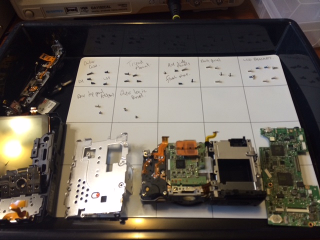
I laid everything out on this magnetic whiteboard (picked up from here).  It’s a beautiful way to do it, and allows you to systematically work through the disassembly process.

The camera is starting to look decidedly unhealthy now: photo 2

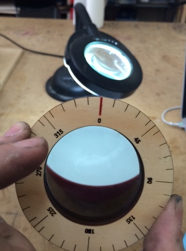
An hour in and the first trouble emerges. I need a torx screwdriver that’s not in my home kit, so I have to pack up and change venue. photo 3

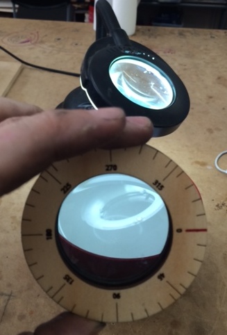
The optical assembly is held onto the main frame by those 3 torx screws, which oppose 3 springs. This allows canon to dial in the flatness of the sensor relative to the frame, and ensure the entire sensor is in focus. Sadly that meant that in order to get to the sensor, I have to destroy the calibration:

photo 4

I didn’t take any photos of the filter, sorry, but I eventually got it removed succesfully and started putting the camera back together:

photo 5

It was starting to look good, but I’d changed around a lot of cables and parts, and I needed to test the camera still worked. I slipped in the SD card and battery, and installed the EF adaptor and my stock lens. Powering up revealed the screen didn’t work, but the camera seemed to respond otherwise (trying to autofocus, etc). I turned it off, carefully took the back off again to reseat both cables to the LCD, and put the case on again.

This time the screen came on beautifully and everything seemed to work fine. Right up until I hit the shutter button, and the camera made a funny noise and went blank. Crap.

I popped the battery out and in again, and tried a couple more times. Seemed like the screen and all the buttons were working, along with autofocus and almost every other feature, but whenever the trigger was pressed it shut down. Hmm… how to troubleshoot. OK, these symptoms could mean it’s a fault in one or more of:

  •  the SD card,
  • the trigger button assembly,
  • the sensor, or
  • the shutter.

How to disentangle these options? Aha! I put the camera to movie mode and hit record. It worked beautifully and I was able to record and play pictures with no problems. That gave a clean bill of health to everything on the list except the shutter mechanism.

Now I had my hint as to where the problem was. I carefully opened the case again and inspected the cables, but everything seemed to be seated correctly. Using a fine tip screwdriver, I carefully advanced the gears I could see on the shutter motor until I heard it click, then moved it around a bit to check it wasn’t getting jammed.

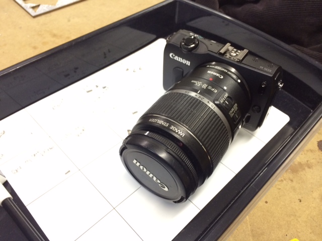
When I reassembled and powered up next, everything was working fine and I was able to take a couple of shots:

First light from the modified camera

First light from the modified camera

After stress testing the camera in a bunch of different modes, shaking it and ensuring that I hadn’t left anything loose, I was pretty satisfied that my evening’s work was done correctly.

Now the sad thing about IR modding your camera at night is that everything looks pretty much the same.

However the next day I managed to have some fun grabbing these pics. These were taken with the modified camera, but with an infrared-only filter added to stop visible light from entering:

IMG_0050

Almost all the foliage seems white. This is know as the Wood Effect (after Robert W. Wood, not cellulose)

IMG_0054

Here’s what the river looks like when I don’t put the 850nm IR only filter on the camera. Note the pinkish tinge of the sky, which is the exact effect that the IR-blocking filter I removed was there to stop:IMG_0055

IMG_0081

So, for $350 and an evening’s tinkering, I managed to get a very flexible sensor that I should be able to use for lots of projects in the future. I’m pretty happy with the outcome.

Posted in Uncategorized | Tagged , | 10 Comments

Water drop photography

Water drop

After my recent experiments into DSLR shutter lag (here and here), I finally got to use my camera the way I was intending.

Set up:

I started out with the kickstarter kit from here which is very well thought out. I’ve begun to make my own arduino based controller a couple of times, then stopped when I realised that my existing controller could actually accommodate what I was after.

I rebuilt everything into a wood frame, and routed the cables and mounted the solenoids so that everything is both extremely portable, and ready to be used without much thought. With unusual equipment like this, I find any extra time needed for setup becomes a psychological barrier to use, and it’s far too easy for stuff to end up permanently unused on a shelf. This is my attempt to avoid the rig becoming the ‘hot-dog maker’ of the photography world.

Lessons Learned:

This was about the third time around for doing drop photography for me, and I think I’m getting the hang of the technique. Here’s some lessons I learned the hard way:

  • Dial it in from basics. First get the DSLR shutter lag set correctly, then get the first drop happening and see if you can progress to a Worthington jet. Only then should you try getting advanced effects like multi-drop collisions.
  • The Mariotte siphon is a nifty technique for getting constant water pressure even as the tank is emptied, and this makes the world of difference when you’re dialling in times in single milliseconds. The company Cognisys have some very well thought out versions for sale here. It wouldn’t be too hard to make your own either.
  • There’s a beautiful ebook here for $20 which describes the process, and gives some amazing examples of what can be done. I printed it in colour and have it in a folder that travels with the rig, and that I keep my notes in.

I got fed up with having good settings one day, and no idea how to get back there the next, so I forced myself to make a spreadsheet. I printed a copy and it lives next to me on the bench. When I get to a particularly interesting settings constellation, I can jot it down for next time:

Here’s the file for it: Settings spreadsheet (XLSX)

Water drop photography sheet

Enough meta, onto the photos!

Photos:

Water drop

Water drop

water drop

IMG_9704

Worthington Jet

Posted in Uncategorized | Leave a comment

Measuring the shutter lag on a DSLR – Part 2

In the last post I explained how I made the LED timing device for measuring the shutter lag on my DSLR.

The first way I wanted to test triggering the camera was by using the IR remote control. If I could get good results with that, then I wouldn’t even have needed to bother making a cable. Sadly it soon became pretty apparent that IR wasn’t going to cut it.

The second part of the testing was hardwired. I examined controlling the DSLR using:

  • a direct connection — Quick and dirty, but possibly has issues with voltage levels and noise.
  • using a 5V mechanical relay — Much cleaner, but might introduce timing jitter due to ‘switch bounce‘.
  • and an opto isolator — This is the ‘proper’ way to do it, and I left this till last, since it’ll stay on the rig when I’m finished.

I then spent quite a bit of time with a pen and paper while the DSLR and shutter rig did their thing.

There’s also a few other things we need to know about the camera which will end up influencing the timing.

  • ‘Mirror lock up’ — A DSLR has a moving mirror that drops down in front of the sensor, which directs the light to the viewfinder. When the shutter button gets pressed, the mirror quickly flips up and the shot it taken. ‘Locking up’ the mirror should in theory make it faster, since it removes a step in the process.
  • ‘Live View’ — when the mirror is flipped up and the sensor is fed to the camera’s screen live.
  • Auto focus/Manual focus — In auto focus mode the camera moves the focus motor forwards and backwards until it detects the greatest detail. This all takes time, and adds to the variability in the delay. Manual focus should be the most repeatable option.

The results:

And here’s what the results look like for my Canon 550D camera (click for large version):

canon 550d shutter lag graphThis was quite surprising to see. Here’s a few lessons:

  • No matter what I do, it sucks. Even in the best case, with everything in manual and a wired remote there’s still 100ms variation in the output.
  • IR seems to introduce a lot of uncertainty in the output. This was surprising, since I coded the arduino to only output the IR code a single time (as any looping might introduce abiguity over timing)
  • Live view & lockup didn’t help at all, in fact they seemed to make it worse, which suprised me.

I was a bit confused here. Was this just my camera, or does every DSLR behave this way? I set out to borrow as many as I could could get in a couple of days. Here’s the results:

DSLR shutter lag comparison

The Nikon D50 was released way back in 2005, so this is a bit of an unfair comparison to Nikon. The two 600D units I played with behaved a heck of a lot better, which is surprising, since the model is only a year later than my camera, which came out in 2010.

Ah well, at least I have my answer. The water drop photography was misbehaving because my camera is at fault. Now I know how the camera acts, I can work around it by keeping the shutter open longer, and rely on lighting everything with a flash instead. The only downside is I have to make a bit of a ‘tent’ around the rig to eliminate the stray light. The other camera we were using could work without the tent setup.

I’ll post some photos of the succesful drop photography shortly.

And here’s the python code and raw data used to generate the graphs:

canon camera analysis

Posted in Uncategorized | 4 Comments

Measuring the shutter lag on a DSLR – Part 1

A while ago we did some playing around with water drop photography and high speed flash:

Water drop photo

It’s rather satisfying, but getting it all tuned and setting up the shot is not that easy to do. As part of it, I wanted to find out precisely how long takes my camera to respond to the shutter button or IR remote.

The easiest way to do this is to make a device that triggers the camera, then displays a counter that shows the number of milliseconds elapsed. If you point the camera at the display, the photo will show you precisely what your shutter lag is.

photo 3

There’s a couple of difficulties with this approach, though. One is that most LED displays are multiplexed, mostly to simplify wiring and IO requirements. If you try to take a photo of a multiplexed display it’ll show up as either corrupted or blank.

There’s a way around this, basically individually wiring up every segment by hand, so that the microcontroller can display it simultaneously rather than scanning the display.

photo 2

The update code has to carefully turn off the common anode to each digit before updating it. That way if the camera shot occurs half way through the update event, it’s obvious, and the display isn’t ambiguous between two digits.

So, how fast does it actually update the display? A simple way to test that is have the microcontroller toggle a spare pin after each update, and then graph it on the oscilloscope.

photo 1

Turns out that even with my crappy inefficient arduino coding, it’s updating 3 time per millisecond. That should be more than adequate for these purposes.

(Edit — I later changed the code to only update a digit when changed, and this increased the update rate to 7.5 times per millisecond.)

I then added in a an IR LED to mimic the Canon infrared remote, and also relay(green thing on the right) to allow direct triggering of the DSLR via a cable:  photo 4

Testing the test equipment:

This was an interesting project. I started out thinking I could knock it off in an evening, and over the next couple of days I kept realising other ways that I could be getting errors.  I was pretty sure that I’d gotten all the bugs (order of updating displays, turning off commons during modifications, etc), but I wanted an external check that the numbers I was reading off the camera screen were sane.

One way to do this was to film the sequence with a 100fps camera. I stepped through the footage and determined that the 100ms and 10ms digits were incrementing exactly as expected. Fantastic.

The last check I did was to use a logic analyzer, and inspect the bits on the wire. It was time consuming to hooking up a line to each segment of the LEDs, run the shot, then work through the digits one by one, but it gave me the confidence that my display was telling the truth.

close up of logic analyzer and led matrix for camera lag

I’ll post the results shortly.

[Edit: Here’s the code, in PDF form since wordpress doesn’t like some file types. It should be obvious where I’ve used other people’s libraries, etc.]

DSLR_delay_test_v02

Posted in Uncategorized | Tagged , , , | 1 Comment

Thermal imaging close up – Part 2

I made a new mount to hold the lasercutter lens. It’s sized to fit snugly into the rubber mounting of the camera, and there’s a piece of folded copper wire as a removal tab: close up lens with removal tab

Here’s some more close up images:

Coin closeupCircuit board closeup Bolt closeupButton closeup

(By the way, the above images look cool, but you should never trust the display of a thermal imager pointed at metal. Metal has a terrible emissivity, so you’ll end up measuring the reflected temperature of the wall instead. If you really need to measure the temp of something metal, put a small piece of masking tape on it first and then measure the temperature of the tape.)

Posted in Uncategorized | Tagged | Leave a comment