
A while ago I got given an old Scalar-Counter unit (Thanks Gordon!). These machines are a real blast from the past:
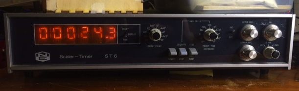
This was built far before LEDs were invented, and it uses a nifty vacuum fluorescent (or possibly neon) tube setup to show the results. There’s a high voltage generator inside, as well as a timer, pulse amplification circuitry and some ‘discriminators’ to limit pulses to acceptable levels.
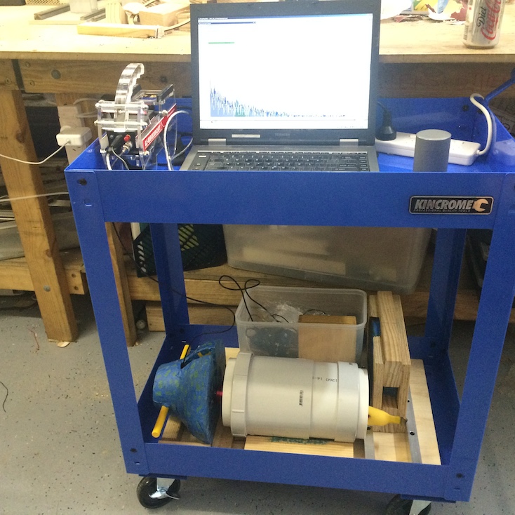
Nowadays if you want to do gamma spectrometery you can get devices quite cheaply that’ll talk to a computer via the sound card, and do the pulse height analysis there. Here’s a pick of my other gamma rig, which I’m planning to document the build on shortly:
Quick test using a banana as a sample and looking for K-40
On the bottom of the trolley is about 100kg of lead and aluminium shielding, and you can just see the red body of the probe sticking out of the white tube. Gamma rays are detected by the probe, amplified by the electronics on the top left, and fed to the computer, where the height and shape of the pulse is analysed, and the energy of the original gamma ray is determined.
The older ST6 does the same job, but can only handle one channel at a time. To make a nice bargraph like the one above, you need a scientist with a pen and paper, and a lot of time.
When I got given the unit, the HV and analyser circuitry worked brilliantly, but the timer wasn’t working. This was a bit of a bummer, as the timer is one thing that makes scalar counters very easy to use. E.g. you can set the unit to count for 10mins and show the number of pulses in that time, or set it for say 10,000 pulses, and have it record the time necessary to count that high.
After pulling it apart and testing some of the circuits, it looked like the problem was a broken crystal.
Normally this wouldn’t be too much of an issue, but I didn’t have a 1.000MHz crystal in my junkbox, and none of the electronics retailers were open on Sunday afternoon. Also, no one seemed to sell a 1Mhz crystal, so I’d have to get a 2Mhz or 4Mhz instead, and make a custom circuit to ‘divide by N’ and create the proper signal. After thinking for a bit, I improvised another solution.
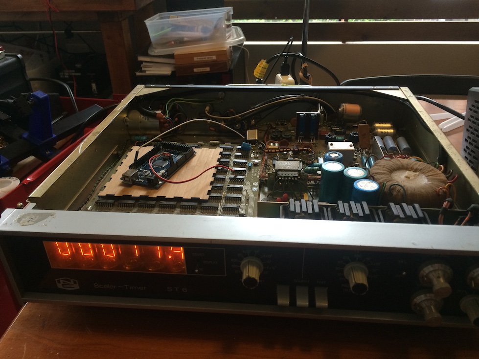
The Arduino Mega has a 16MHz clock, and I wrote some assembler to just toggle a pin off, wait a few cycles, and toggle it on again. 3 wires later:

Silver box at the top is the broken crystal, being replaced by the arduino on the left
And the counter was back to life.
Now counting happily
Once it was working, I mounted the circuit properly to the case and sealed it up again.
It might seem wasteful to sacrifice a $20 (yay ebay!) microcontroller rather than use the ‘proper’ $2 crystal, but once you factor in the time and effort of getting in the a suitable part and possibly designing a divider circuit, I was happy to pay the convenience tax this time.

There’s a good chance I have a vintage 1MHz crystal that would fit right in… and I think I even know where!
LikeLike
I’ll make sure to give you a ring next time, Kean 🙂
LikeLike