
Examination of the Hypothesis:
The hypothesis I put forward in the last post I think has great merit. In particular:
- This hypothesis explains the consistent presence on the dodecahedra of their two most defining features; the nodules and the varying holes, and furthermore, my hypothesis has the enormous advantage of requiring both parts as essential and optimal parts of the design.
- The nodules are optimal for string winding, being reliably ‘undercut’. Other proposed functions of the nodules (such as hand grips) are significantly less plausible.
- The varying diameter circular holes are optimal for cone mounting. No other hole shape (pentagon, etc) is as easily mounted. Consider If the device served some other function, with the nodules being functional, but the circular holes being an optional aesthetic feature, then (given the sheer number of artefacts found) we would expect to find at least one craftsman having decided to omit them, resulting in either:
- a dodecahedron without holes,
- or perhaps a skeletal ‘cage’ dodecahedrons with no faces altogether,
- or other variants with non-circular cutouts (such as pentagonal holes).
To my knowledge, none of these hypothetical variants have been found.
- The literature has, shall we say, a superabundance of hypotheses on what the dodecahedrons were for, but most ideas strongly focus on explaining either the holes or the nodules. I haven’t seen any that provide compelling explanations for both features at the same time. To my knowledge, this is the first hypothesis to do so.
- This hypothesis explains the reason for differing hole sizes, since they are needed to fit a tapering cone. Furthermore, we require the differing holes to occur not just randomly, but in rough pairs. Since inserting the cone to rest on the bottom face requires the upper face to be large enough for the cone to pass through. If the holes in the dodecahedron were just used for measuring diameter (e.g. as a pipe gauge), there would be no reason to expect that opposite holes should be similar in size.
- This hypothesis explains the almost total lack of standardization encountered in the dodecahedrons. They don’t need to be any particular size, weight, or absolute diameters, and can be made as small or large the customer would prefer and materials to hand suit.
- This hypothesis explains the reason why the instrument is both specific enough to require many different sized holes, yet relaxed enough for us to encounter dodecahedrons which have no obvious markings on the faces to delineate them. Since this information would be carried on the accompanying cone, it is redundant to carve on the dodecahedron itself. While identifying markings on the face may be present, choosing to carve them on the faces would be an aesthetic rather than functional decision.
- Contrast that with other proposed uses of the holes (such as pipe gauge, or rangefinder), where not only would the absolute size be important, but correct identification of the which face to use would be absolutely vital to the successful operation. It is simply not plausible that a plumber or craftsman verifying a part would be required to rely on either memory or sight to identify which of the 12 different hole sizes a given face corresponded to, when that information could easily be carved on the faces permanently.
- This hypothesis also has the potential to explain why ‘Roman’ dodecahedrons have not actually been found in Rome, but instead are found in Gallo-Roman areas. Since the Romans had their own calendar of a more irregular nature, it’s not as neat a fit, and becomes a ‘harder sell’ to adopt.
- If an open and free device that one might sell, it might simply have flopped and not found Roman interest, since 30 is a not-significant number to them as far as calendars go.
- Alternately the calendar may have been a cultural secret. Either because if knowledge that those-people-who-are-in-our-empire had still not adopted the official Julian™ calendar, they might send some soldiers out to give them a talking to, or alternatively because it was thought to involve secret cosmic and nature knowledge that was not for sharing.
- It also explains the existence of a lesser known Roman Icosahedron, since both dodecahedrons and icosahedrons have 30 edges, both can be used as calendars. Furthermore, it correctly predicts that a Roman Icosahedron will not feature the same varying hole patterns as the dodecahedrons, since the 20 faces are not useful for counting months.
Falsifiable tests:
Any good hypothesis should have at least some conceivable observation which would allow it to be proven wrong. So I’ll stick my neck out and suggest a few ways this idea could be disproved:
(Disproving should ideally require finding a couple of examples, btw. Since perhaps one faulty dodecahedron may be a workshop manufacturing blooper, or made as a practical joke (similar to teapots with no hole in the spout), but consistently finding examples of dodecahedra which are not functional as calendars would blow this idea out of the water.)
- The nodules must be undercut to retain string. Finding dodecahedra with nodules that are tapering spikes (instead of ‘wasp-waisted’ balls, or at the very least cylindrical pegs) would disprove the usage of string, since it would too easily slip off.
- The holes, should be circular and varying in diameter. (Either in a linear fashion or in a looping fashion for an Analemma display). Finding dodecahedra with identically sized holes would disprove the usage of a cone. Only if the dodecahedral faces contain unique identifying marks, (which would allow identifying the month in the absence of the cone), could we relax this requirement.
- Opposite holes must not have widely dissimilar sizes. If the cone is longer than the dodecahedron, as seems most likely for a vivid display, then putting a small hole directly opposite a large one would prohibit the large one ever being used, since the cone could not pass through the dodecahedron far enough to engage the large hole.
- Note that the requirement for opposite faces to be in rough correspondence, but not necessarily adjacent in the sequence potentially allows falsifying any other hypothesis which might require alternate faces to be adjacent in size.
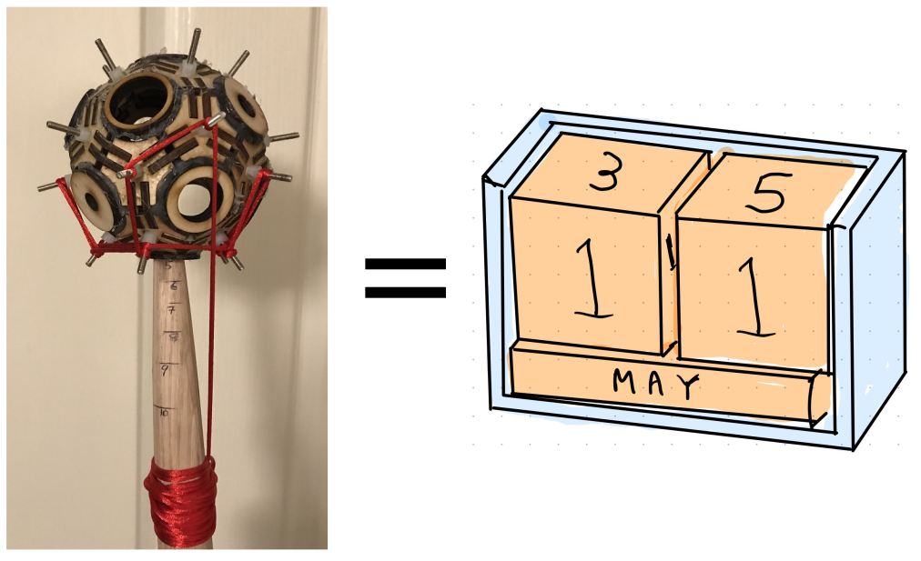
- For each pair of holes the inter-hole spacing and the difference in diameter allow us to calculate the minimum taper on a cone that fit both without fouling, and hence calculate the maximum possible cone length. As a rule of thumb, I would suggest any implied cone length of less than, say, 120% of the dodecahedron face spacing would disprove the calendar hypothesis, as this would not produce an obvious enough vertical travel to show the month clearly. (This is an aesthetic judgement on my part, but I do want to stick my neck out and make it falsifiable. I would be surprised if any were below 150% in practice).
For example, assume we have a dodecahedron of height 50mm, with a linearly arrangement of holes of diameter [10, 12.5, 15, 17.5, 20, 22.5, 25, 27.5, 30, 32.5, 35, & 37.5mm]. How should we place the faces?
-
- If we placed the 10mm and 30mm faces opposite, the cone must taper from 30mm to 10mm within 50mm, which would imply the longest possible cone length was only 68.75mm, barely larger than the dodecahedron itself. This does not make an impressive display.
- If we instead place the 10mm and the 17.5mm holes opposite, then the tapering implies a maximum cone length of 183.3mm, which is much more visible a change throughout the year, with the dodecahedron moving more than 3x its height.
- Naturally, if we place holes in adjacent size order, we have the most freedom. With 10mm and 12.5mm holes opposite each other, then the tapering implies a maximum cone length of 550mm. We are free to shape our wooden cone to any value smaller than this, of course, and may choose a smaller number if that suits our scepter or walking stick of choice.
4. Any Roman Icosahedrons (with 20 sides instead of the dodecahedron’s 12) should definitely not have faces with the same differing hole pattern that the Roman Dodecahedons do. This is because that, whilst a dodecahedron can be re-positioned on its 12 different faces to show the month, using the 20 faces of the icosahedron in the same way would not perform any useful task for calendar keeping. Rather than using the icosahedral faces directly, we may instead use the 12 vertices (nodules). This may be accomplished by, e.g. by putting a ring, ribbon or other marker on one nodule to show the current month. For this reason we may expect that the icosahedrons will not have unique identifying marks to delineate the faces, but, if present, will have markings useful for delineating the vertices instead. However unique marks are not strictly required either for dodecahedrons or icosahedrons.
Further Predictions:
The following are predictions which are verifiable, but not directly falsifiable:
- If an analemma scale is used, then then the obvious choice of information to mark on the faces would be to show the months containing equinoxes or solstices (furthermore, equinoxes are more likely to be marked than solstices, since the largest and smallest holes likely correspond to the months containing solstices)
- If all or most of the holes have markings, and they are not just month numbers, then the next most useful piece of information to include would be an indicator of whether the given month was 29 or 30 days long.
These suggest a subsequent line of research, verifying that the tests above hold for the available data.


