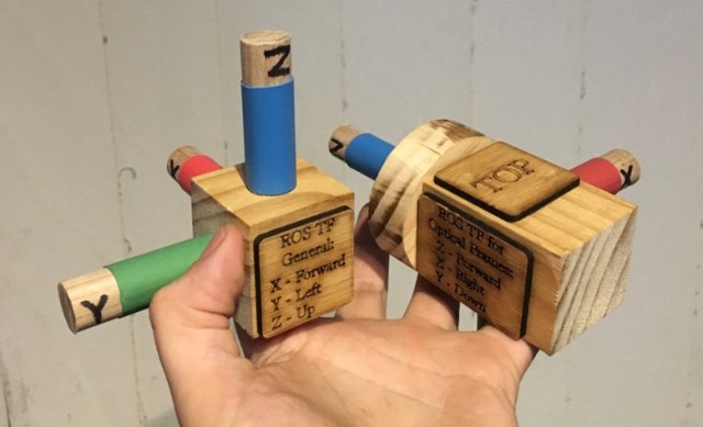
I spent a bit of time recently help a friend set up a robotics lab. One of the things I wanted to nail down was a consistent set of coordinate frames for all the equipment.
The Robot Operating System is awesome, and provided you set up your TF models correctly, it’ll do all the work for you. However it’s sometimes counterintuitive how it should be set up. ROS has a standard way of arranging coordinates (REP0103), but it’s different for ordinary coordinate frames and camera frames. (For very good historical reasons; the camera frame has Z pointing forwards, which means X is lined up with image columns, and Y is image rows).
I decided to make some tangible models for people to use when they’re discussing transformations. When troubleshooting robots you constantly find yourself in front of a whiteboard making “finger axes”, I wanted something we could use instead, and that had the same colouring and labels as the software.
The idea is first, to have something tangible to play with while brainstorming, and second, as a reminder of the convention, to allow errors to be detected. If there’s an error, I really want someone to ask “Wait, why is the green arrow pointing in a different direction on screen?”.
I’ve been getting interested in plein air oil painting recently, not so coincidentally after Netflix brought out some inspiration.
As with any set of tools, painting equipment only has value if you actually use it, and lots of hobbies get dropped, not because people don’t enjoy them, but because it’s slightly too hard to use regularly. Adam Savage has a great saying, that “drawers are where tools go to die”, i.e. if it’s out of sight, we forget it’s there, and we’re not motivated to look for it.
Hence, I wanted to make sure I had a way to make it easy to get painting. To make getting going on any given day require the absolute bare minimum of ‘spritual energy’, gumption, spoons or other resources that might be running low.
Enter the pochade box! Pochades (from the French for pocket) are an all-in-one way of carrying around supplies and a way of working on paintings in the field.
My wishlist of features was something like this:
Must allow stopping and starting just by opening & closing the box
No pack up time, fussing to turn canvases around, add clips, put them in separate boxes for transport.
Must allow carrying of essentials & tools:
Paints, brushes, small amount of solvent & mediums, pencils, etc
The two exceptions to this are a roll of paper towels, and the (leakproof) brush washer tin, which I’m happy to carry in my backpack.
Tools should be exposed for easy use during painting.
This was my major peeve with the French easel design, by hiding stuff behind the canvas, I’m likely to forget it’s there, or be too lazy to use it when I should.
Wet canvas carrier
Utterly essential. Nothing’s going to add stress to the end of the day like manouvering a wet canvas around safely.
Multiple sizes of canvas able to be carried
Many pochade boxes are single size only, and lots of artists end up owning three or four different sized boxes, no joke. Of course having a separate small box is much lighter for quick trips, but still flexibility is handy.
Should sit flat on a desk, and not take up too much room if I’m sharing a desk with others
This one is more a response to some French easel style pochade boxes I saw. They claim to fold up the tripod legs and allow you to use it on a desk in a class environment. It might be just me, but if I’m indoors with a group, I’d feel extremely self conscious having a huge folded tripod on the desk.
Weight goal: Hmm… ‘Luggable‘.
Lightweight would be good, but I’m aiming for something I can carry a few hundred meters from a car, rather than something you can climb a mountain with.
Glass palette as mixing surface
Easy cleanup, also allows putting reference material underneath
Should be removable, as it allows storing unused paint in the freezer
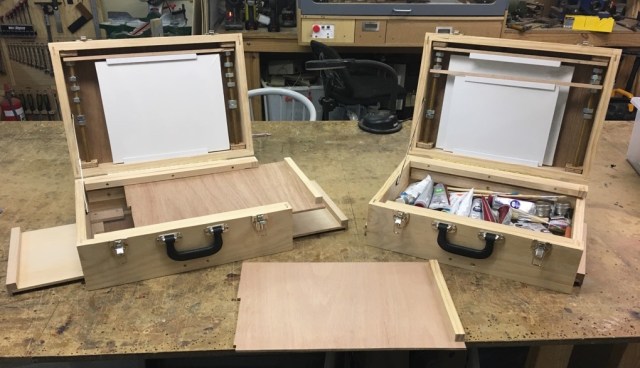
I took my time playing around with ideas for this one. After more than a week of sketching and researching other people’s designs, I had some idea of what I wanted to do.
This is the final result. (Why are there two? At some point through construction, I realised I’d put enough safety margin in my wood purchase to make a whole other box, and I couldn’t resist having a matched set).
Here’s what I came up with for wet canvas storage, it’s adjustable to any size canvas, and you can have a pair of different sized wet canvases in place without them touching:
I was inspired by this pochade from Ruth Vines, but modified it so the rods don’t extend out of the box.
The boards are held in place by plastic extrusion used for sliding cupboard doors. The wooden pieces have ‘U’ cutouts and can be completely removed by loosening the nuts and just sliding the frame out. The lower frame has a cutout allowing taller canvasses to pass through:
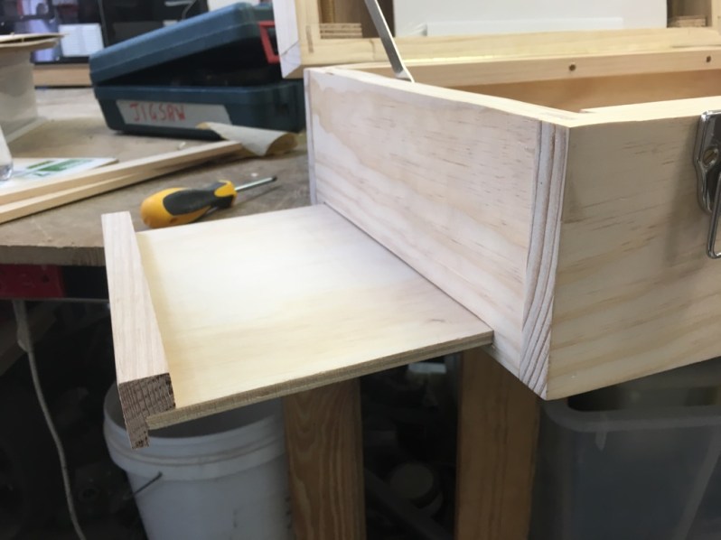
Both of the box sides have a pullout work surface, something to rest brushes, solvent containers and other miscellaneous bits on:
I might add in some cutouts to act as brush or tool holders
The glass palette surface was just a $5 A4 photo frame screwed to the surface. This has the added bonus that I can put a printed sheet underneath to help me get consistent palette ordering, and a value scale to compare against while painting:
For some reason the hackerspace printer was making the greyscales at the bottom green? Meh, I’ll fix it later
And of course the palette can be removed & stored in the freezer (to keep the paints wet as long as possible)
The final thing to do was add something to differentiate the two boxes, so I can grab the right one in a hurry. Using the obligatory naming convention I made a couple of lasercut labels:
Sometime I’ll probably put a polyurethane coating on for protection, but they’re pretty sturdy.
I’ve had a chance to carry them around a bit now, and while they’re not light, they’re acceptably ‘luggable’, and I can carry one a kilometer or two without major injuries. They’ve also proved more than sturdy enough to use as a seat while waiting for a train!
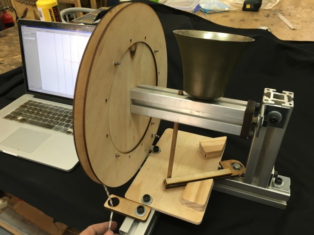
Quick and dirty post showing something I made this morning to aid in troubleshooting the filtration system at Robots and Dinosaurs.
Members from RnD have been building and rebuilding our own lasercutters for years. Mostly building our own because we got started before readymade commercial lasercutters of a decent size were affordable to the hobbyist, and if you wanted a machine you needed to spend six months whittling your own from lumps of aluminium. (Nowadays most cheap Ebay lasers are probably the place to start) But filtering the fumes has always been a bit of a dark art.
We’ve both made filters from scratch, and bought various commercial filters. Every filter is some combination of a coarse pre-filter, bag filter/wool filter, then putting the output through an activated carbon bed.
Getting a filter that works isn’t the hard bit. It’s getting one that won’t clog up after a week’s use that’s tricky.
Recently we changed lasercutters, and getting the filter going again nicely has been tricky. There’s been discussion about putting fans before or after the inlet, the arrangement of the bags, and which bits are sealing well.
Anyhoo. It occurred to me that a lot of the problem has been that it’s tricky for us to figure out when something’s changed, if the filter’s full, or if a given modification makes the situation better or worse.
After a quick trip to the hardware store, and also getting some pneumatic fittings from my toolkit, here’s what we’ve got:
The U-shaped tube contains water and food dye, and was filled with equal amounts of sucking, blowing and cursing.
I drilled in the case of the lasercutter, on a point which connects to the exhaust plenum, and made sure it seals tightly. Note the use of the air fittings allows us to disconnect the gauge from one point and measure from another, so we can narrow down pieces of equipment during troubleshooting.
During use the gauge doesn’t change by much. This is showing the delta pressure between the lasercutter body and after the first pump:
I’ll add an adjustable scale to it shortly, but it’s not a bad indicator for now. We’ll probably play around with measuring the pressure between various locations while we’re troubleshooting.
And what better way to show the indicated signal than Mehdi’s most famous feature:
Here’s a vid of it in action:
I wasn’t expecting this bit, but in hindsight there’s no reason why it shouldn’t. When I was replaying the above video, the detector happily triggered again on the 2nd generation audio:
Browception
The Teensy is really a nice platform to make this happen, cheap and very arduino compatible, and there’s a ton of work gone into those audio & FFT libraries. It was a joy to play with.
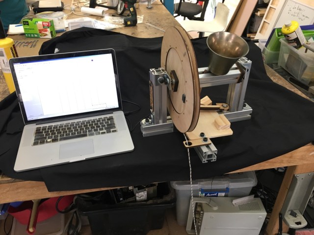
I’ve recently gotten into Change Ringing, and helped a friend build a bell simulator from a broken bell that was laying around.
“Full Circle” bell ringing is a bit counter intuitive. Rather than having the mouth of the bell face down as you’d expect, the bells are over-balanced resting on a stop, so the slightest pull causes them to ring through 360* of travel.
Also, since the mass of the bell can be much more than the bellringer, they can’t start or stop the bell instantly, but instead can excerpt just enough force to comfortably shift maybe one position behind or one position ahead in the sequence.
The nifty consequence of this very mechanical limit, is that change ringing then becomes an exploration of the permutations possible with the sequence of bells. There’s a whole bunch of tasty mathematics in there, touching on graph theory, permutations, polyhedra, Hamiltonians, and much more.
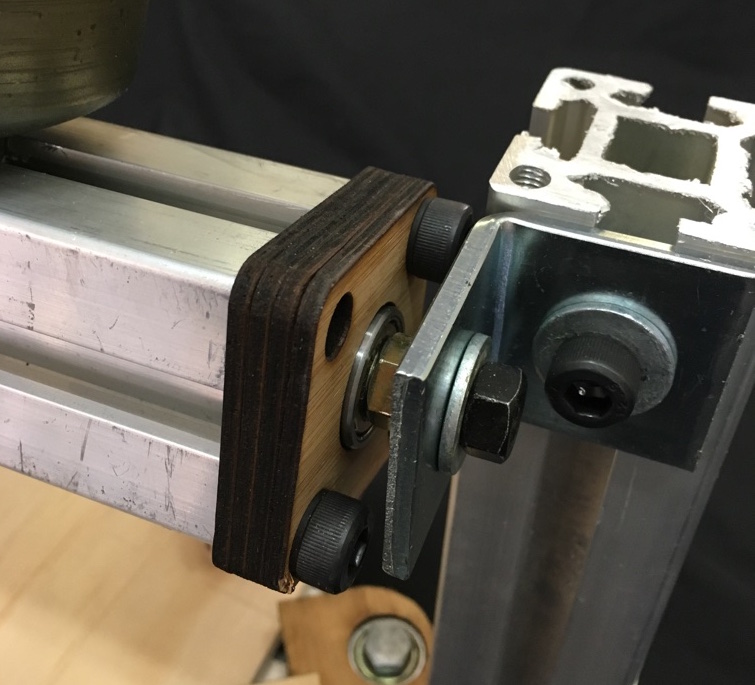
Back to the hardware. Here’s what I came up with, it’s pretty cheap, and should be compatible with all major Campanology simulators like Abel & Virtual Belfry:
Note the ‘slider’ bar at the bottom can slide to allow the bell to rest stationary regardless of which side it was raised from
The main frame is made from the bulk aluminium extrusion I bought previously, and the bell is supported on some cheap 608 skate bearings held in lasercut wooden holders.
The wooden dowel used for the “stay” has been sized so that if the bell is rung up too vigorously, it breaks there, rather than anywhere else. (This much more import with the big bells, often weighing tons, as it means a $5 piece of wood is damaged, rather than the bearings, frame or bell itself).
The electrical parts needed are quite cheap, and cost only about $30:
Wiring is absurdly straight forward. 5V to 5V, GND to GND, and the signal from the sensor goes to the CTS signal on the serial.
All the electronics are mounted on the side. I used a cheap plastic box we had laying around the space.
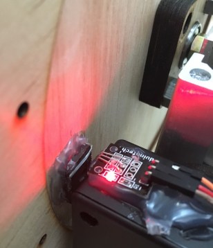
Once that’s done, a small magnet is hot-glued to the wheel so that it triggers the sensor at the resting (bell down) position.
The light on the hall effect sensor is very handy for tuning
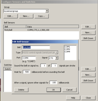
Back to the computer. In Virtual Belfry, the bell is selected to use the COM port, and the CTS signal. It’s then just a matter of tuning the delay between the sensor firing and the bell striking.
This is the true reason for my previous project on Platonic Solids. I was playing around with map projections, and became a tag smitten with Buckminster FulIer’s Dymaxion Projection.
It’s able to do a map projection with surprisingly little distortion:
Living in the 21st Century is very convenient. I was able to download the SVG from Wikipedia, and it took about hour’s work to get something suitable for lasercutting. Not perfect, but way better than tracing manually.
The vertices are sized to allow an M3 screw to hold without needing any nuts, or pointy self-tapping screws.
I quite liked the aesthetic of the cap heads, compared to the countersunk or dome heads used in the last post.
Files are here for anyone that wants to make their own:
This started because I wanted to make my own copy of Buckminster Fuller’s Dymaxion Map. Lasercutting mitre joints & gluing them leads to big seam lines on the map, as well as being hard to hold while gluing. Instead, I decided to make a row of holes and try sewing the faces together:
If you look closely, you can see the exact limit of my patience.
But the stitching was a bit time consuming, as well as being difficult to retighten.
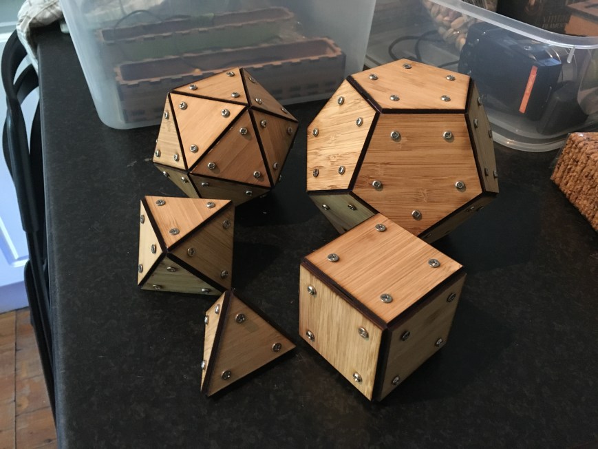
Instead, I had the idea of using 3D printed vertices, and screwing lasercut tiles into them:
With a bit of playing around with angles, and parametric design, I made the whole set:
Clockwise from top left: Icosahedron, Dodecahedron, Cube, Tetrahedron, Octahedron.
I’m pretty happy with the construction method. Sure, it’s not exactly light on screws, but I rather like the aesthetic, and it’s extremely strong. I can stand on the icosahedron and it takes my weight with no problems.
Also, the nice thing about this approach is that to make a larger object, all you need to do is recut the wooden parts, and the 3D printed vertices can stay the same.
Files here for anyone that wants to make their own:
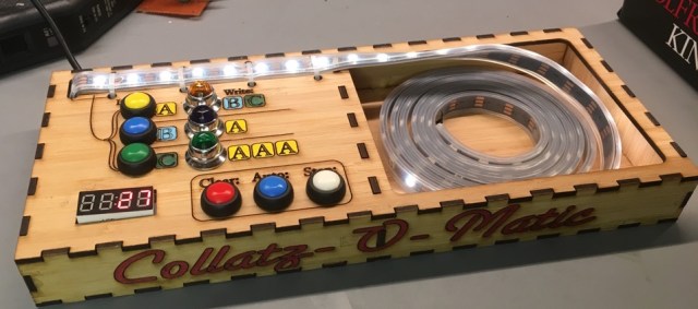
Are you sick of having to work out the Collatz Sequence by hand? Run out of whiteboard space? Hand cramping up with all your scribbling? Then you need my latest project, the Collatz-O-Matic!:
Shown with LEDs spooled, ready for computation on the go
This came about because after the previousposts on Cellular Automata, I sent a link to Stephen Wolfram, he kindly emailed back and said he thought it was cool. However the email ended with: (emphasis mine)
I think in all these years nobody has yet actually implemented this…
Darn it, that sounds like a challenge.
I had actually already planned out what my next project was going to be, but unfortunately my brain felt this was enough of a nifty concept to make me drop what I was doing and start sketching tag systems. After a brief dialog with my shoulder angels, I gave in.
APost Tag System is a method of computing very similar to a Turing Machine. There’s an array of symbols, or a tape, or a queue, however you want to call it, and a simple series of operations are performed on it at each timestep.
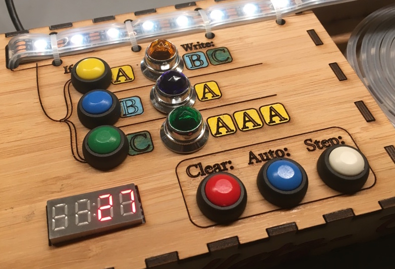
My machine is set up to follow the Collatz conjecture, which we’ll describe shortly. Every step the following things occur:
2 tags are deleted from the start of the tape
If the first symbol deleted was:
A – then write BC to the rear of the tape
B – then write A to the rear of the tape
C – then write AAA to the rear of the tape
That’s it. That simple behaviour is enough to implement the [modified] Collatz sequence below. (If the number is even, then divide by 2. If odd, then multiply by 3, add one, and divide by 2. )
By the way, the Collatz conjecture is still an unsolved problem in mathematics. So far every positive integer tested flows to 1, but it’s not yet been formally proved that all positive integers will.
Back to the tag system! I started looking at systems with rolling balls, as Stephen Wolfram suggested. Hooking up a couple of servos to sort of sluice-gate the flow of balls from a set of hoppers is fairly doable. There are a number of ways to detect the different types of balls, but a colour sensor is probably easiest. I got some cedar spheres from the dollar store and started prototyping.
Computing in action.
Hmm… how many balls would I need? Based on wanting to calculate the Collatz sequence for each number 1 to 30, working out the maximum intermediate values for each… average ball size 23mm… let’s see…. length of the track is… Two hundred and twelve meters.
OK, perhaps a tad too ambitious for a quick project.
As an alternative strategy, I decided to use LED strip as the ‘tape’, and make a very simple interface with an arduino. Here’s how it works:
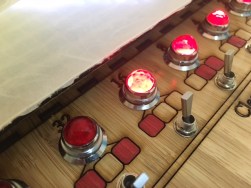
When the machine’s stopped, the A/B/C buttons add that symbol to the end of the tape.
If the tape holds only ‘A’s, ( no ‘B’s or ‘C’s), then update the numeric display at the bottom left to show the current number
Each step two symbols are deleted from the start of the tape, the corresponding rule lamp is lit up, and new symbols are added to the far end of the tape.
Clear button stops or resets the display, ‘Step’ runs one step of simulation forward (until the next number in the sequence is reached), and ‘Auto’ runs the sequence until it reaches 1.
Here’s the machine in action:
Fun fact, if you try and start from 27, then the machine will break! That’s because the values go up to 9,232 on the way to reaching 1. My (inefficient) code uses a byte per tag symbol, and the arduino only has ~2k of memory, so I run out of space long beforehand!
I put in some code to detect the tape running out, and here’s what it looks like after a few minutes of churning away:
Your modern electronics are no match for the might of the number 27.
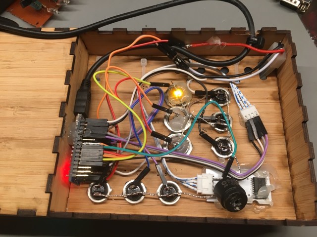
Inside the machine is an Arduino Nano, some LEDs and switches, and a couple of meters of Adafruit Neopixels
Not my finest work, but it should be reasonably sturdy
The files are up on Thingiverse here for anyone that wants to make their own:
I’ve left space for a 7 segment display on the right hand side, to show the rule number in Wolfram Notation. Sadly I don’t have any in my parts bin just yet, so it’ll stay blank for a while.
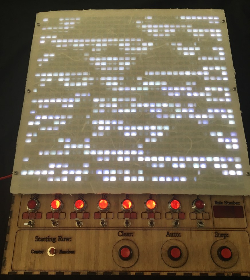
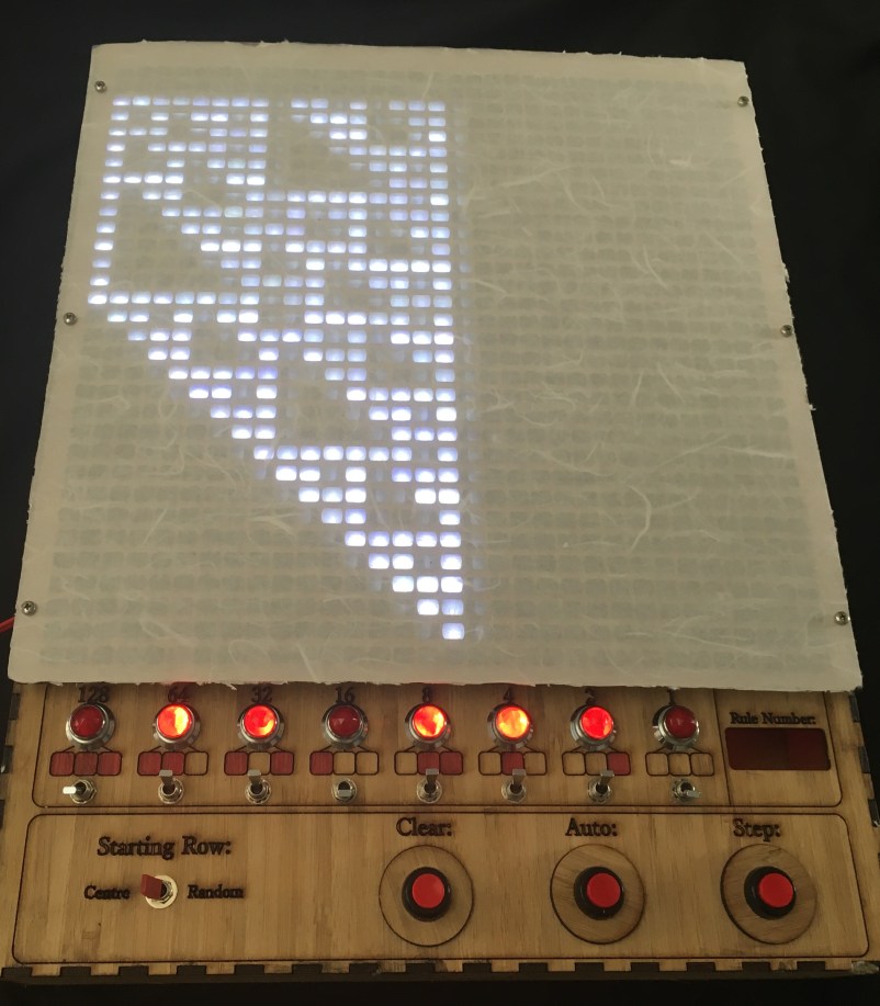
I spent ages playing with various diffusers for the LED matrix, and settled on this combination of rice paper with a clear polypropelene layer for protection.
The lasercut mask underneath is rectangular, but with rounded edges. I wanted something to show the connectivity in the simulation was much stronger in the horizontal (“Space”) direction than in the vertical (“Time”) direction.
The colour matching of the LEDs looks much worse in this photo than in real life. Also occasionally these photo will ‘lie’ as to whether a single pixel was lit or not, since the LEDs are PWM’d to get brightness control.
Down the bottom left is a switch to specify whether the sim should start with a random configuration, or with a single centre pixel.
There’s three buttons to control the sim, Clear, Step (takes a single step) and Auto (steps continuously while held).
It’s rather satisfying to play with different rules and see how various patterns emerge:


